

Technical Solutions
SeerFabric Intelligent Lossless Data Center Solutions
1. Background and challenges
With the rise of cloud computing, big data, artificial intelligence, Internet of Things, and 5G networks, data is showing explosive growth, and it also puts forward more stringent requirements for data center construction, and how to build to meet the business development in the next 3 to 5 years The need is a proposition that every data center practitioner needs to think about.
The traditional idea of building a high-performance data center is mainly to promote the upgrading of data center network bandwidth on the one hand and then drive the upgrading of networking architecture (I .e. 10G/40G model evolves to 25G/100G networking model, and then evolves to 100G/400G model); On the other hand, intelligent management technologies such as SDN Telemetry are introduced to realize automatic and intelligent operation and maintenance management of the data center network, and finally realize the integration and upgrade of "control analysis.
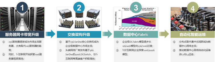
(Figure 1: Traditional data center solution upgrade road)
However, the three major pieces of data center infrastructure: computing and storage have made great progress in recent years. Among them, computing, on the basis of CPU, has seen processor chips such as GPU and TPU that are generated for specific scenes and services, and the computing efficiency has been improved by hundreds of thousands. Storage, SSD all-flash products have appeared on the basis of HDD mechanical hard disks, and the access efficiency has also made a qualitative leap. Although SDN technology has appeared in the network, its kernel essence is still TCP/IP technology, and TCP/IP processing mechanism is "best effort", involving "large processing delay of TCP/IP protocol stack" and "high CPU load caused by protocol stack processing mechanism", and there is not much improvement:
TCP/IP protocol stack processing delay is large:
1. TCP protocol stack needs to do multiple context switches when receiving/sending messages, and each switch takes about 5us ~ 10us delay;
2. As well as at least three data copies, relying heavily on CPU for protocol encapsulation, the protocol stack itself has a fixed delay of tens of microseconds, making the protocol stack delay a significant bottleneck in AI artificial intelligence and SSD distributed storage-microsecond systems;
Server CPU load is high:
1. In addition to the fixed delay problem, TCP/IP also requires the host CPU to participate in the protocol stack memory copy many times. The larger the network scale is, the higher the network bandwidth is, and the greater the scheduling burden on the CPU when sending and receiving data is, resulting in a continuous high load on the CPU.
2. According to industry calculation data, it takes 1Hz CPU resources to transmit 1bit data. When the network bandwidth reaches more than 25G (full load), most servers, at least 50% of CPU resources will have to be used to transmit data.
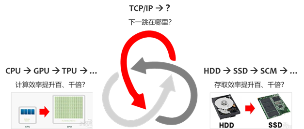
(Figure 2: Is TCP/IP the shortest board in the barrel?)
Based on this, where is the next hop of TCP/IP?
2. SeerFabric intelligent lossless data center solutions
2.1 technology development trend 1:RDMA timely born
In the process of data packet processing, the traditional TCP/IP technology needs to be processed by software applications and operating systems first, which takes up a lot of server resources and memory bus bandwidth resources. In this process, there are many problems such as data copying, interrupt processing and complex TCP/IP protocol processing, which inevitably leads to excessive network delay.
RDMA(Remote Direct Memory Access) technology is called "Remote Direct Memory Access", which is a technology that is generated to solve the delay of server-side data processing in network transmission. Data in user applications can be transferred directly to the server storage area, and data can be quickly transferred from one system to the storage of remote systems through the network.
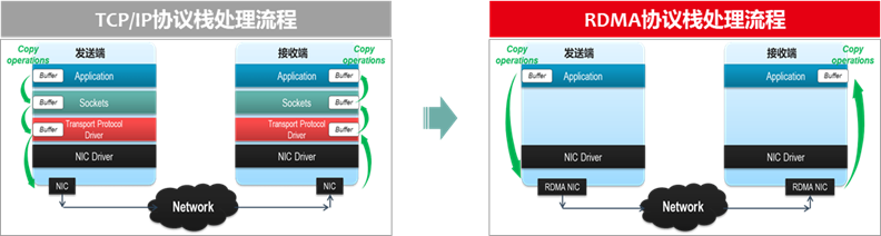
(Figure 3:TCP/IP and RDMA protocol stack processing flow comparison)
RDMA technology realizes the direct transfer of data buffer between two nodes in the process of network transmission. In this node, the data can be directly transmitted to the memory of the remote node through the network, bypassing the multiple memory copies in the operating system. Compared with the traditional network transmission, RDMA does not need the intervention of the operating system and TCP/IP protocol stack, data processing with ultra-low latency and transmission with ultra-high I/O throughput can be easily implemented, and the intervention of resources such as a remote node CPU is basically not required, and excessive resources are not required for data processing and migration.
RDMA technology appeared earlier in Infiniband networks for the interconnection of HPC high-performance computing clusters. The traditional network communication based on Socket Socket (TCP/IP protocol stack) needs to go through the operating system software protocol stack, and data is copied and moved back and forth between the system DRAM, the processor Cache and the network card Buffer, thus occupying a large amount of CPU computing resources and memory bus bandwidth, and also increasing the network delay.
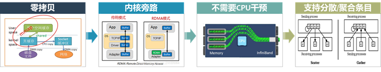
(Figure 4: What are the technical advantages of the RDMA protocol?)
For example, 40Gbps TCP/IP streaming can exhaust all CPU resources of mainstream servers, and RDMA technology is a good solution to the technical pain points of traditional TCP/IP communication. For example, in the 40Gbps scenario, the CPU utilization rate of servers using RDMA technology will be reduced from 100 to 5%, and the network delay will be reduced from ms level to less than 10us, even more in extreme scenarios. Therefore, the advantages brought by RDMA technology are obvious. At the same time, RDMA technology can be used in almost all traffic scenarios in the data center, for example, there are four scenarios: application-to-application, computation-to-computation, computation-to-storage, and storage-to-storage, and the improvement in data center data reading efficiency is obvious.
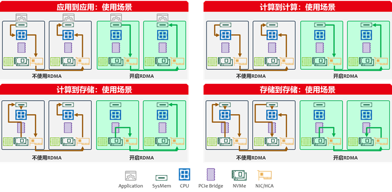
(Figure 5:RDMA technology in four scenarios traffic simulation)
2.2 Technology Trends 2: Introduction to RDMA Technology
At this stage, RDMA network technologies are mainly Infiniband, RoCE and iWARP. Infiniband network mainly appears in HPC high-performance computing scenarios. Because of its own technical characteristics, everything used in this technology is dedicated, including application programs, programming interfaces, network protocols, network cards, network equipment, hardware interface forms and even management software. iWARP is based on the RDMA technology of TCP/IP protocol, which is defined and published by IETF standard. This article is limited by space and focuses on RoCE technology.
RoCE technology is based on Ethernet RDMA technology. Emulex and IBTA(InfiniBand Trade Association, InfiniBand Industry Association) jointly announced the launch. Up to now, two versions have been released. The latest RoCEv2 version replaces IB's GRH(Global Routing Header) with UDP Header IP Header. RoCE v2 works on UDP, uses UDP 4791 ports for transmission and supports routing, so it is sometimes called routable RoCE, or RRoCE for short.
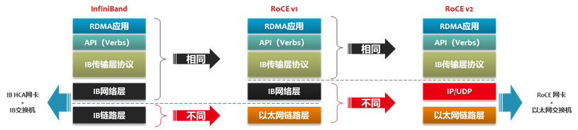
(Figure 6: Evolution and comparison of mainstream RDMA technologies)
2.3 technology development trend 2:RDMA lossless network technology
At the beginning of its proposal, RDMA was carried in a lossless InfiniBand network. The Infiniband network provides a perfect packet loss retransmission mechanism. For InfiniBand architecture, the receiving end can only receive ordered messages. If packet loss occurs, the flow will be interrupted. When packet loss occurs, the receiving end will send NACK (not ACK denial character) control message with PSN (packet sequence number message sequence number) to the sending end, to retransmit the lost message and subsequent messages.
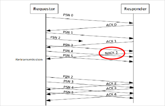
(Figure 7: InfiniBand-based retransmission mechanism)
However, when RDMA technology is applied to Ethernet, Ethernet is essentially a "best-effort" network, because Ethernet lacks a perfect packet loss protection mechanism and is extremely sensitive to packet loss. A packet loss rate of more than 0.1 (1‰) will cause the effective throughput of the network to drop sharply to 75%. However, 1% packet loss makes the effective throughput of the network almost drop to 0. Therefore, RDMA throughput should not be affected, the packet loss rate is preferably guaranteed to be less than 1 in 10,000 (0.1 ‰) or even less than 1 in 100,000 (0.01 ‰), I .e. there is preferably no packet loss.
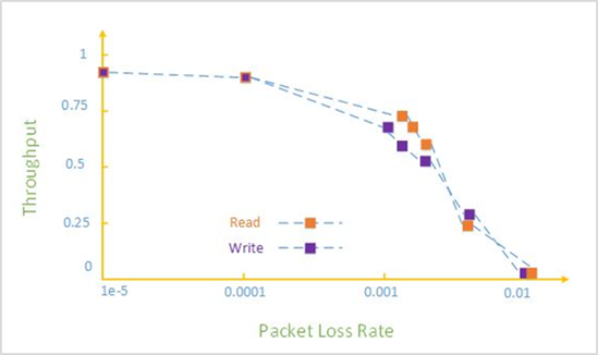
(Figure 8: Traditional Ethernet lacks a complete packet loss protection mechanism)
However, the design concept of native Ethernet is a "best effort" network, not a lossless network. Therefore, lossless Ethernet network requires PFC priority-based flow control (Priority-based flow Control,IEEE802.1Qbb), ECN display congestion notification (Ethernet Congestion Notification,IEEE802.1Qau), DCBX data center bridge Bridging Exchange Protocol (IEEE802.1Qaz) and ETS enhanced transmission selection (Enhanced Transmission Selection,IEEE802.1Qaz) four technologies are completed, of which Ethernet layer is mainly PFC, ETS and DCBX; The IP layer is mainly ECN; The IB transport layer is mainly ECN, and the service processing flow is roughly as follows:
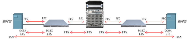
(Figure 9:RDMA lossless Ethernet computing scenario technology panorama)
PFC and ECN are two mandatory technologies. Generally, recommend PFC is a two-layer technology and ECN is a network layer and transport layer technology, PFC and ECN can be enabled at the same time, and recommend be enabled at the same time in the RoCE environment, so as to ensure that the RoCE packet has no packet loss and the network bandwidth is guaranteed. From the perspective of giving full play to the high-performance forwarding of the network, it is generally recommended to adjust the buffer waterlines of ECN and PFC to make ECN faster than PFC trigger, that is, the network still continues to forward data at full speed, allowing the server to actively reduce the packet rate. If the problem cannot be solved, the upstream switch is allowed to suspend message sending through PFC. Although the throughput performance of the whole network is reduced, packet loss will not occur. The two technologies cooperate with each other to finally realize network lossless.
2.4 SeerFabric Intelligent Lossless Data Center Solution Panorama
With the help of nearly 20 years of accumulation in the network field and the understanding of industry customers' business, the SeerFabric intelligent lossless data center solution is released. The whole solution is based on the cloud-edge AI collaborative architecture, which can build intelligent lossless control models for different business scenarios with the help of intelligent learning, realize intelligent identification of business scenarios, and then complete dynamic matching of corresponding model parameters, with high bandwidth, low latency, zero packet loss, accurate forwarding and deterministic network experience, it widely serves the digital transformation of important industries and fields such as the Internet, government, finance, production and entertainment, and high-performance computing.
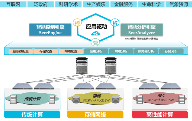
(Figure 10:SeerFabric Intelligent Lossless Data Center Solution Architecture)
SeerFabric intelligent lossless solution covers computing, storage, network switching, management and control, performance presentation and optimization of end-to-end large bandwidth, delivery delay, accurate forwarding with zero packet loss and deterministic network experience. From the solution architecture, it can be divided into management and control analysis layer and ICT infrastructure (network, computing and storage) layer, the application scenarios are mainly divided into traditional computing scenarios, storage network scenarios and high-performance computing scenarios. To achieve the unified integration of the three scenarios, the management and control analysis layer is a crucial link, mainly the intelligent control engine SeerEngine and intelligent analyzer SeerAnalyzer to carry the implementation. SeerEngine realizing the construction of scenario-based business traffic model and model matching, realizing the dynamic control of intelligent lossless network, SeerAnalyzer realizing end-to-end fine data acquisition and lossless performance status visualization, and using AI-ECN algorithm according to performance status data to complete the dynamic intelligent tuning calculation of network equipment ECN waterline.
AI-ECN fully realize the combination of data, intelligent algorithms and professional knowledge, and intelligently empower SeerFabric intelligent lossless solutions.
End-to-end fine-grained performance indicators are Telemetry in data collection, fully exploiting the fine performance data collection capabilities of intelligent network cards, storage and H3C network devices, enabling intelligent algorithms to perceive RoCE traffic components and sizes, dynamic changes of network device cache queues, etc. Data items include various performance statistical indicators of interfaces and queues, and RoCE streaming session statistics listened by network devices. At the same time, through the cooperation of Agent and intelligent network card deployed on the server, the dial-test capability of RoCE traffic is provided, and the network can be visually debugged and tuned before the service goes online. Supported RoCE smart network cards include Mellanox series network cards, Intel E810 network cards, etc.
In the algorithm, the real experimental environment collects performance KPIs under different traffic models, and forms a training data set after labeling through the real experience of the application, and generates an ECN waterline dynamic tuning model after modeling and offline training with expert knowledge. The AI-ECN tuning algorithm model has the characteristics of high efficiency and small amount of calculation, and supports two modes of centralized tuning of controller and distributed local tuning of network equipment. For example, in the centralized tuning mode, ECN waterline tuning can be started under large-scale network management without a special AI chip and using a control analysis cluster equipped with Intel XEON-SP servers. In local mode, network switches equipped with Intel XEON-D and ATOM can complete tuning with only a small CPU overhead.
3. SeerFabric solution value and highlights
Smart: AD-DC-based applications drive the data center
SeerFabric intelligent lossless data center solution SeerAnalyzer intelligent analyzer to support the implementation of network and connected storage and computing resources, based on AI learning and expert knowledge, network, computing, storage resources, to build a differentiated data center scenario intelligent lossless network analysis model. SeerAnalyzer intelligent analyzer to monitor RoCE basic data in real time, and collect information including ingress/egress packet loss count/total, ingress/egressPFC count/total, ingress/egress buffer usage, ECN, headroom buffer usage, Ingress/egress threshold overrun times, etc. At the same time, the analyzer will also collect RDMA real-time alarm reporting information, key information, such as ingress/egress packet loss alarm information, Headroom buffer overrun packet loss alarm information, egress buffer overrun alarm information, and configuration change information through Netconf operation, is SeerAnalyzer to collect the above network big data information, so as to train the network model based on business, gain insight into the network, and make multi-dimensional real-time evaluation, statistics, induction and visual presentation, further realize accurate root cause analysis, and realize anomaly prediction and trend analysis, and finally through the SeerEngine intelligent controller to achieve intelligent linkage and network optimization, closed-loop self-healing network, for the user business protection escort.
For AI artificial intelligence computing scenarios, the maximum N value supported by the buffer does not overflow when sending Burst traffic. To achieve this requirement, the network equipment needs to work in the "Lossless" lossless mode. For the scenario of the N:1 Incast model, seerFabric intelligent lossless solution supports the SeerAnalyzer collection of network big data through intelligent analyzers and the distribution of parameters to the network foundation based on AI algorithms.
SeerFabric intelligent lossless data center solution supports deep buffer-based tuning and AI ECN tuning based on link bandwidth utilization. For example, when link bandwidth utilization exceeds 90% and 95%, switches realize service balance of bandwidth and delay through AI ECN function.
Convergence: Ethernet unified three scenarios to achieve data center business convergence
The traditional storage SAN network scenario has always been dominated by FC(Fabric Channel) optical fiber switches. Since 2017, in the global data center storage market, the market share of flash disk (SSD, Solid-State Drive) has exceeded that of mechanical hard disk (HDD,Hard Disk Drive). Up to now, some industry customers have started to run enterprise production business on SSD storage. NVME-of the storage scenario replaces the traditional FC SAN network, the focus should be on: the server discovers the disk device through manual configuration and establishes a long connection with the disk device. If the server does not receive the packet sent by the disk device for a long time, it is considered that the disk device is faulty, and the storage traffic is switched to the standby path.
The SeerFabric intelligent lossless data center solution supports the intelligent lossless storage network technology solution, namely iNOF(Intelligent Lossless NVMe Over Fabric, intelligent lossless storage network), which is a technology that integrates Ethernet and storage network. Through cooperation with LLDP(Link Layer Discovery Protocol, Link Layer Discovery Protocol), all devices in iNOF can automatically sense the server and the addition and departure of disk devices in the first time, so that the product can intelligently adjust the relevant configuration, and ultimately help to achieve storage traffic in the Ethernet without packet loss, high throughput transmission. SeerFabric intelligent lossless data center solution iNOF has advantages over traditional NVMe technology:
Plug and play: When a host accesses the iNOF network, other hosts already in the iNOF network will quickly discover the newly joined host and automatically initiate a connection with the new host.
Fault intelligent fast sensing: When a link of a host accessing the iNOF network fails, the iNOF switch will quickly notify other hosts in the iNOF network of the failure, and then the other hosts can intelligently sense fast jump.
Ultra-wide: Large bandwidth supports 400G networking evolution
The SeerFabric intelligent lossless data center solution supports mainstream data center switch products, namely box networking and box networking, covering 10G/40G networking model, 25G/100G networking model, 100G/100G networking model and 100G/400G model;
In view of the disadvantages of low FC bandwidth and high cost in the DCI scenario of data center interconnection, SeerFabric intelligent lossless solution provides a 400G ultra-long distance lossless network solution, which is 4 times higher than that in the industry. At the same time, combined with intelligent controller SeerEngine and intelligent analyzer SeerAnalyzer, automatic operation and maintenance management of storage network can be realized, effectively reducing user operation and maintenance costs and user workload.
Previous Page
Next Page
Previous Page
Next Page
Contact Us
-
Address: 1-2-1605, Botai Building, Nanmenwai Street, Nankai District, Tianjin
Telephone: 86 15263826658
E-mail:zhangping06112106@126.com